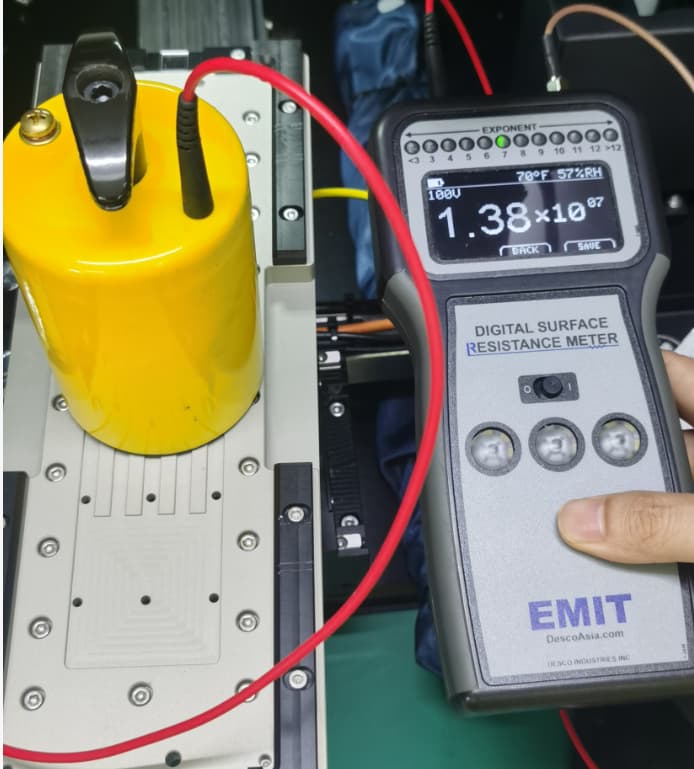
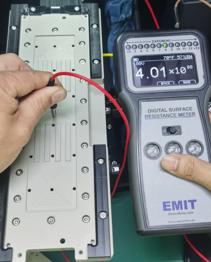
I would like to ask what the compliant method for measuring the ground system resistance of the automated equipment operation platform is? Currently, we have two measurement methods internally as follows: 1. Use a heavy hammer electrode, with one test line connected to a heavy hammer electrode placed on the operation platform and the other test line connected to the ground system to test the ground resistance of the operation platform. 2. Use alligator clips, with one test line connected to an alligator clip touching the operation platform surface and the other test line connected to the ground system to test the ground resistance of the operation platform. I believe that the ground resistance test of the operation platform should use a heavy hammer electrode to test the ground system resistance (because the heavy hammer electrode simulates the large-area contact of objects with fixtures in actual use, fully testing the full-path resistance from “fixture surface → material → ground terminal → earth”, and truly reflecting the static discharge capability). Which of the two methods is more recommended as the standard measurement method?
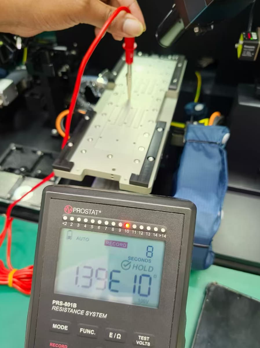
First of all, thank you for your answer. Currently, we have a problem. When we measure the system resistance to ground using a five-pound electrode, it is qualified. However, when we measure the resistance to ground using the second alligator clip in the above picture, it is unqualified (exceeding 10 to the power of 9). I think it is caused by the influence of contact area and weight. So, I want to use a heavy hammer electrode to measure the resistance to ground. Is this more reasonable?
Most likely the plate may be anodized which would make the alligator clip hard to have a connection. The 5 pound electrode would be fine to measure that.